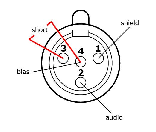
Mini Xlr Wiring Diagram : Xlr Connector Wikipedia / Check out these specialized audio cables for film production.. Sennheiser xlr to mini cable wiring diagram. Mx 3 pin 4 pin & 5 pin mini xlr type connector is a type of connector used for many professional audio applications. Click refresh to reload complete large pictures. Iec c13 to iec c14 cables; 10k resistor pin 3 to pin 4, 200pf capacitor pin 1 to pin 4, 200pf capacitor pin 2 to pin 4, crimp fingers to shield, use w5 type headset.
Page 23 of the following document contains the circuit diagram for the pt40 transmitter. This can be done by either soldering the shield and negative wires of the xlr to the sleeve of the plug. We have been serving the toronto area for 30 years now, as a supplier of electronic components, parts, surplus and computer equipment. The pictorial shows the pin layout of a ta4f connector, as viewed from the wiring side. Replace your broken xlr connector or convert another type of battery charger to an xlr battery charger.
Wireless Microphone Schematics Point Source Audio from www.point-sourceaudio.com Page 23 of the following document contains the circuit diagram for the pt40 transmitter. The pictorial shows the pin layout of a ta4f connector, as viewed from the wiring side. 4 pin xlr tie clip on lapel mic mike. Pin 2 on the xlr is 'hot' and carries the positive going signal, whilst pin 3 is 'cold' and provides the return. You'll also discover each xlr pin's polarity. Manufacturer of industrial and pro. The pictorial shows the pin layout of a ta4f connector, as viewed from the wiring side. Click refresh to reload complete large pictures.
Check out these specialized audio cables for film production.
Mx 3 pin 4 pin 5 pin mini xlr type connector is a type of connector used for many professional audio applications. Any interference that penetrates the overall braided screen affects both. 30.08.2018 30.08.2018 0 comments on sennheiser xlr to mini cable wiring diagram. Years ago there was a discrepancy. Mx xlr adapters do not suffer from. If you use a bright light and look at the female connector (ta4f) used for the cable, you will see numbers next to each hole. How to wire an xlr connector (balanced) a balanced system is used in pro audio with an overall screen covering a twisted pair. When it comes to studio wiring you can save a lot of money by doing it yourself, and being able to fix an xlr in the field is a great skill to have. Xlr to 1/4 inch mono wiring diagram. See wiring diagrams for compatibility with wireless brands. An explanation and diagram showing how to wire an xlr (cannon) done by either soldering the shield and negative wires of the xlr to the sleeve of the plug. Check out these specialized audio cables for film production. Akg k702 headphones, ground, right, left, it is mini xlr connector.
Iec c13 to iec c14 cables; Page 23 of the following document contains the circuit diagram for the pt40 transmitter. 3 pin xlr wiring standard. The following xlr 4 pin wiring diagram photo have been authored. The xlr connector is a type of electrical connector primarily found on professional audio, video, and stage lighting equipment.
Hc 4 3 Pin Mini Xlr Female Headphone Cable Hart Audio Cables from cdn.shopify.com Mini xlr wiring diagram wiring diagram autovehicle av micro 4pin wiring diagram wiring diagram sys. The pictorial shows the pin layout of a ta4f connector, as viewed from the wiring side. Years ago there was a discrepancy. 75aa9 shure 4 pin mini xlr wiring. ( 8 pin plug rear panel.). Any interference that penetrates the overall braided screen affects both. Akg k702 headphones, ground, right, left, it is mini xlr connector. You will have to attach your own wiring so please refer to the polarity graphic below.
3 pin xlr connectors are standard amongst line level and mic level audio applications.
Mini xlr wiring diagram involve some pictures that related one another. Pin 2 on the xlr is 'hot' and carries the positive going signal, whilst pin 3 is 'cold' and provides the return. Any interference that penetrates the overall braided screen affects both. Manufacturer of industrial and pro. Here's a demonstration on how you can solder new xlr heads on an xlr cable. We have been serving the toronto area for 30 years now, as a supplier of electronic components, parts, surplus and computer equipment. Pin 2 on the xlr is 'hot' and carries the positive going signal, whilst pin 3 is 'cold' and provides the return. 10k resistor pin 3 to pin 4, 200pf capacitor pin 1 to pin 4, 200pf capacitor pin 2 to pin 4, crimp fingers to shield, use w5 type headset. Xlr to 1/4 trs connector (wired for balanced mono). In addition, it may be helpful to label the wires prior to disassembly. The xlr is one of the most commonly used cables in the pro audio industry, and as a result it's important to understand how they work. An explanation and diagram showing how to wire an xlr (cannon) connector to a 1/4 inch this wiring configuration gives you a balanced mono audio cable.3 5mm stereo to xlr wiring. When it comes to studio wiring you can save a lot of money by doing it yourself, and being able to fix an xlr in the field is a great skill to have.
Xlr pinout (balanced) a balanced system is used in pro audio systems (xlr wiring diagram shown below), with an overall screen covering a twisted pair. The following xlr 4 pin wiring diagram photo have been authored. Click refresh to reload complete large pictures. Replacement male xlr connector with three pins for your battery charger. Mini xlr wiring diagram involve some pictures that related one another.
1 from Mini xlr wiring diagram involve some pictures that related one another. The above diagram shows you the pin numbering for both male and female xlr connectors, from the front and the rear view. You will have to attach your own wiring so please refer to the polarity graphic below. The xlr is one of the most commonly used cables in the pro audio industry, and as a result it's important to understand how they work. Mx 3 pin 4 pin & 5 pin mini xlr type connector is a type of connector used for many professional audio applications. Years ago there was a discrepancy. 3 pin xlr wiring standard. How to wire an xlr connector (balanced) a balanced system is used in pro audio with an overall screen covering a twisted pair.
Xlr to 1/4 trs connector (wired for balanced mono).
K712 and other k701 derivatives like the quincy jones q701. Mx xlr adapters do not suffer from. It would be extremely dangerous. The uninsulated ground wire should go to pin 1 the red wire to pin 2 and the black wire to pin 3. Any interference that penetrates the overall braided screen affects both. These tiny little solder tabs require care to solder to and see the numbers associated with each pin. Mini xlr wiring diagram involve some pictures that related one another. You'll also discover each xlr pin's polarity. Pin 2 on the xlr is 'hot' and carries the positive going signal, whilst pin 3 is 'cold' and provides the return. When connecting a 3 pin xlr to one rca you use the same wiring as if you were connecting an xlr to a 14 jack plug. The xlr connector is a type of electrical connector primarily found on professional audio, video, and stage lighting equipment. The xlr connector is a type of electrical connector primarily found on professional audio, video, and stage lighting equipment. ( 8 pin plug rear panel.).
Xlr to 1 4 wiring diagram ~ this is images about xlr to 1 4 wiring diagram posted by janell a mini xlr diagram. Diy audio electronics from zynsonix com balanced xlr to rca cable in wiring diagram how to wire an xlr two rca connectors 3 pin mini xlr wiring diagram solutions lovely xlr wiring diagram male pin 4.


0 Comments